Aerial Mapping: Treehouse Brewing

Collection of survey images taken 6/20/24, 7/3/24, and 7/30/24 of the Saratoga Treehouse location currently under construction.
Use the layer panel to select the imagery to display. In addition to the google basemap and my aerial surveys, the project plan submitted to the Saratoga Planning Board is also included as a transparent overlay.
The images are all large format tif files so they may be slow to load.
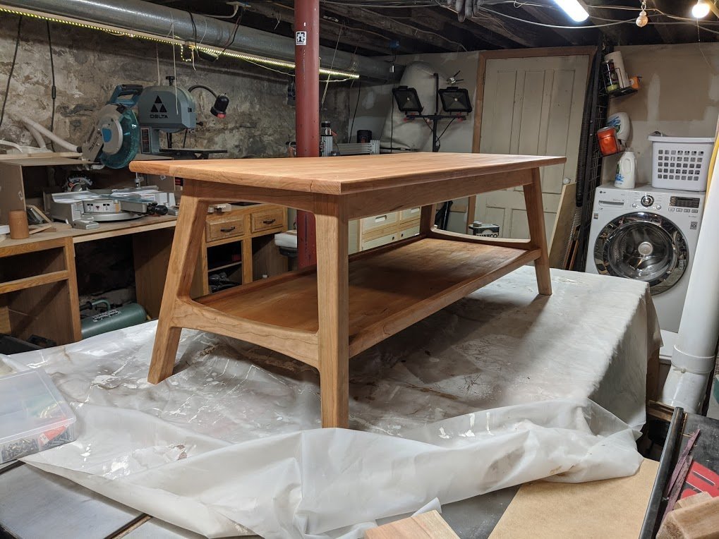
New Coffee Table

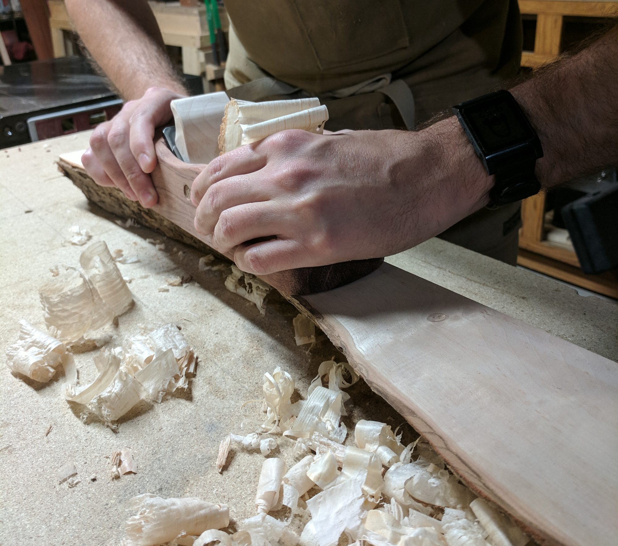
I decided to make a build video for my latest piece of furniture . I shot all the video on a phone camera so some of the scenes have auto-focus/white-balance issues, but it captures a good view of the overall process.
Watch the whole build here, with details on the build after the video.
I used templates on this build to simplify things. I started off by making an MDF template for the leg shape, and for router guides for the mortises using my CNC machine.
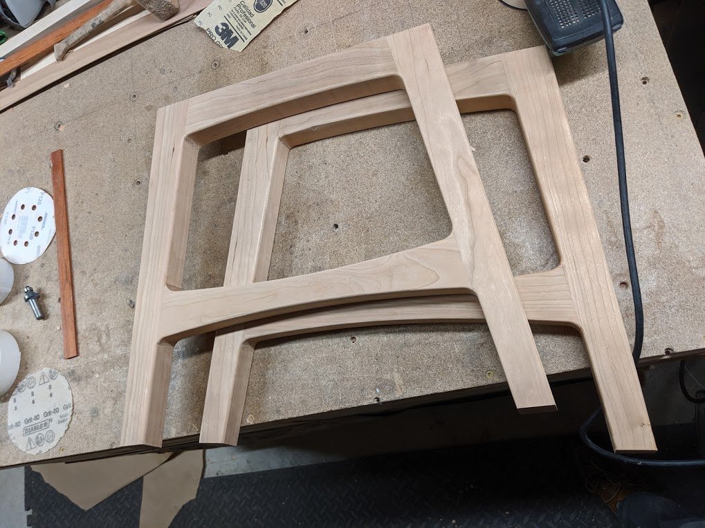
This method allowed me to create fillets (rounds) between joining pieces without having to perfectly cut each piece. It also makes all the manual cutting much less critical as everything is cut over-sized.
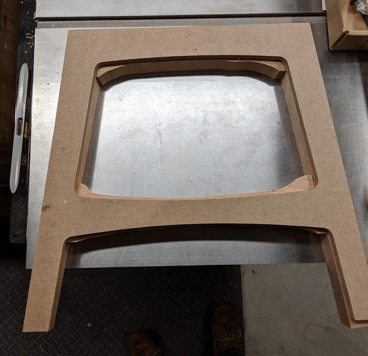
Templates also make it easy to make two exact matching sides, or additional tables.
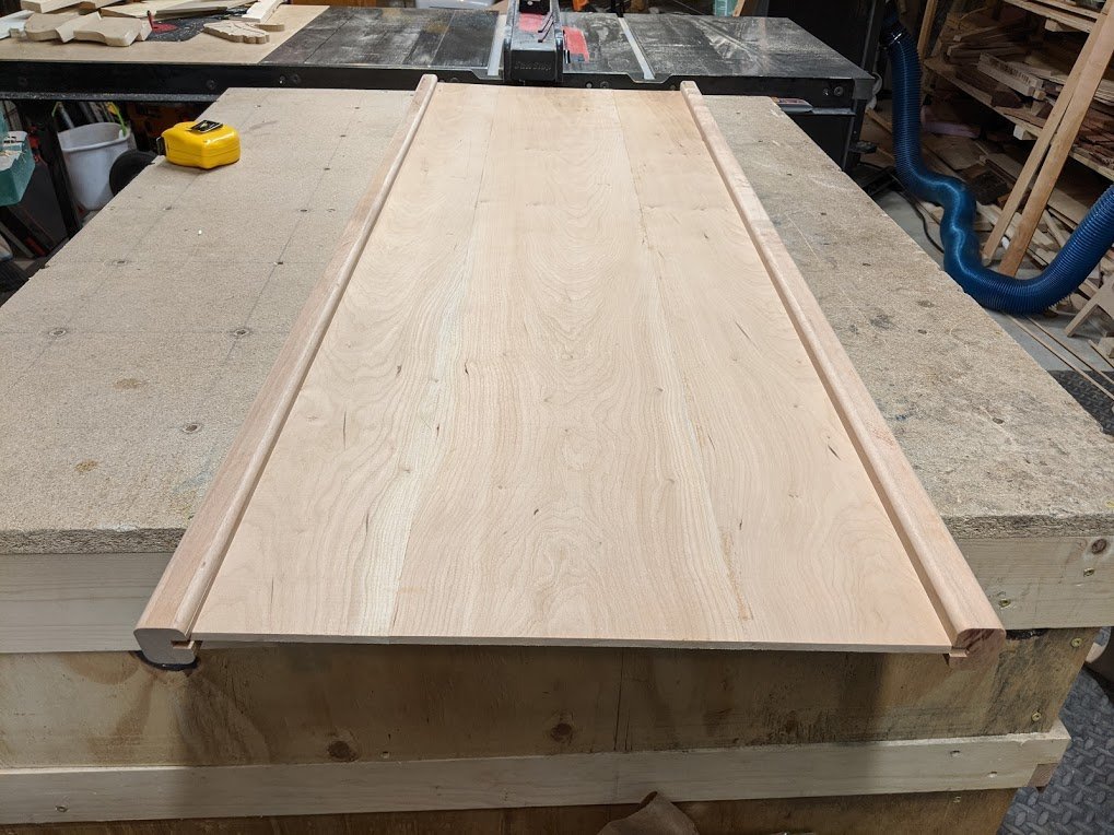
This table was the first major build with the new band saw, so I decided to resaw my own 0.20″ thick panels for the lower shelf out of a single 5/4 board. I did not show it on the video, but there are some small stretchers on the bottom of the panel to stiffen it a bit. The shelf panel is not glued, but trapped in a slot on all sides.
Prior to final assembly, I finished the top and shelf with polyurethane. After assembly, I added additional coats to the top and shelf, and applied the first coats to the leg assembly.
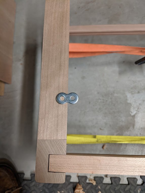
The top is attached with figure 8 fasteners (one is shown below, please note this is before glue up as you can see the visible joint is not seated fully). After shooting the video, I went back and added 2 extra fasteners, one on each side stretcher to better distribute the load if the table is lifted from the middle with items on the lower shelf.
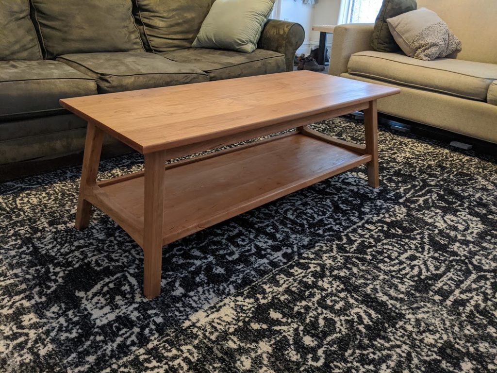
The table looks excellent in my family’s living room!
Glycol Chiller Unit

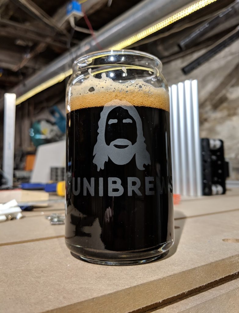
Some of you may know from my second Instagram account (@funibrews) that I have been brewing lots of beer this past year. That hobby has spawned a number of interesting projects that I decided to share.
The Chilling Issue
During the fermentation phase of brewing, temperature influences the flavors created by the yeast. Traditionally classic beer styles were brewed seasonally, exploiting the ambient temperatures and were very dependent on the region. For a home brewer looking to brew a variety of beers year round this can be very limiting.
Keeping your beer warm is easy, as electric heating pads are cheap and easy to operate (I’m using the FermWrap). Additionally the yeast digestion is exothermic, and will generate its own heat during peak fermentation.
On the cooling side, home brewers can either control the environment temperature, or try to control the beer temperature directly.
On the environment side, the common option is a refrigerator dedicated to fermenting. By controlling a refrigerator to run at fermentation temperatures you can influence the beer temperature. This method doesn’t work great with multiple fermenters however, as each might be at different temperatures depending on their stage of fermentation.
The direct beer temperature control option uses a coil in, or jacket on, the fermenter to circulate coolant to shed heat from the beer. On the home brew side, ice water is typically used as a coolant, as its cheap. Ice requires maintenance however, as it will melt and warm over time.
The professional option is a glycol chiller unit that runs a refrigeration cycle to maintain the temperature of a coolant. These coolers have started to pop up on the homebrew scene, but cost over one thousand dollars…. this is where my homemade homebrew chiller comes in.
In this article I will cover just the glycol unit side of my build, not the integration with the fermentor. Stay tuned for a future article on that build!
The Build
For the refrigeration unit, I sourced an old 6,000 Btu/hr air conditioner. I found an old one no one was using, so it was free (lets hope it lasts).
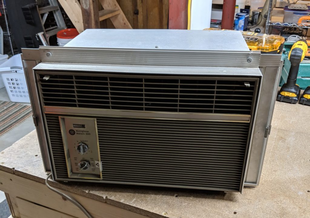
An AC works with a vapor compression/expansion cycle, meaning a compressor runs, causing heating of the refrigerant on one side of the unit, and then the refrigerant expands through a valve causing the opposite side of the unit to get cold. There are two fans, one to cool the hot side, and one to blow air into the house through the cold side. For my application, I wanted the cold side to cool my glycol but still needed the hot side to shed heat.
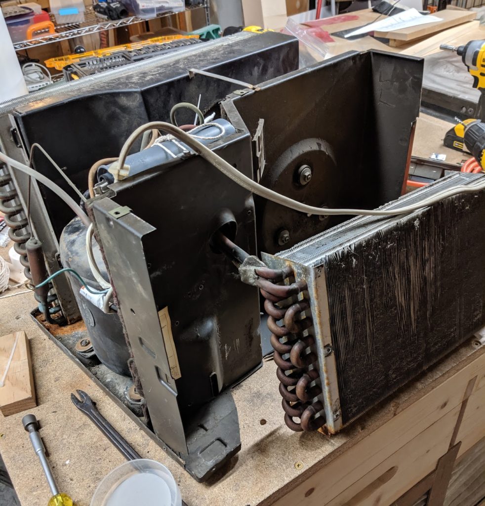
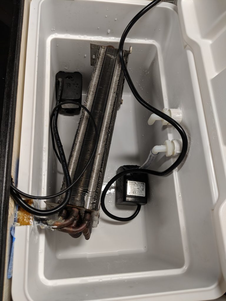
The cold side fan was removed, but the hot side fan was left in place. The cold side heat exchanger was moved out to the limits of its plumbing for better access. Most of the old AC housing was removed, leaving only what was needed to support the components still in use.
I searched for a while to find the perfect sized glycol reservoir. I ended up going with a very basic Coleman cooler to hold the glycol and keep it insulated. It holds a bit over 4 gallons.
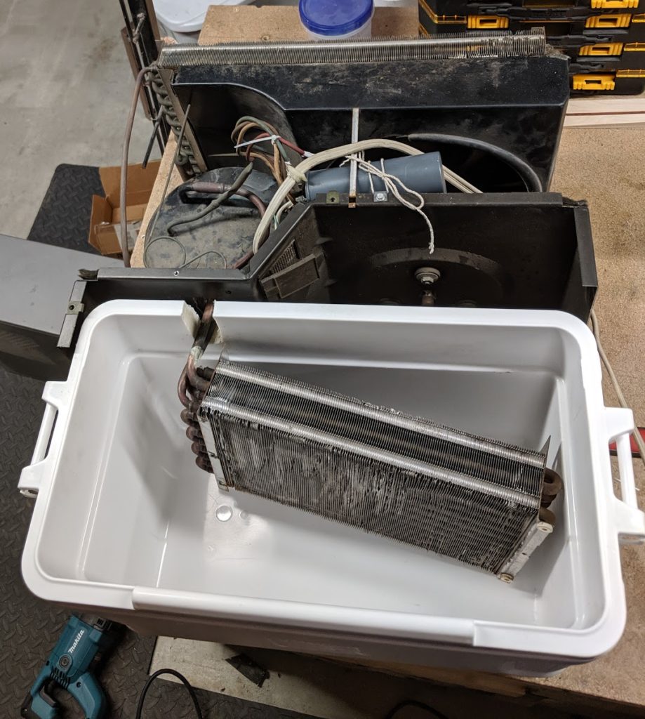
The cooler was cut to allow clearance for the AC plumbing. I chose a cooler that had a similar footprint as the AC.
To keep everything together, I built a wooden frame with coaster wheels.
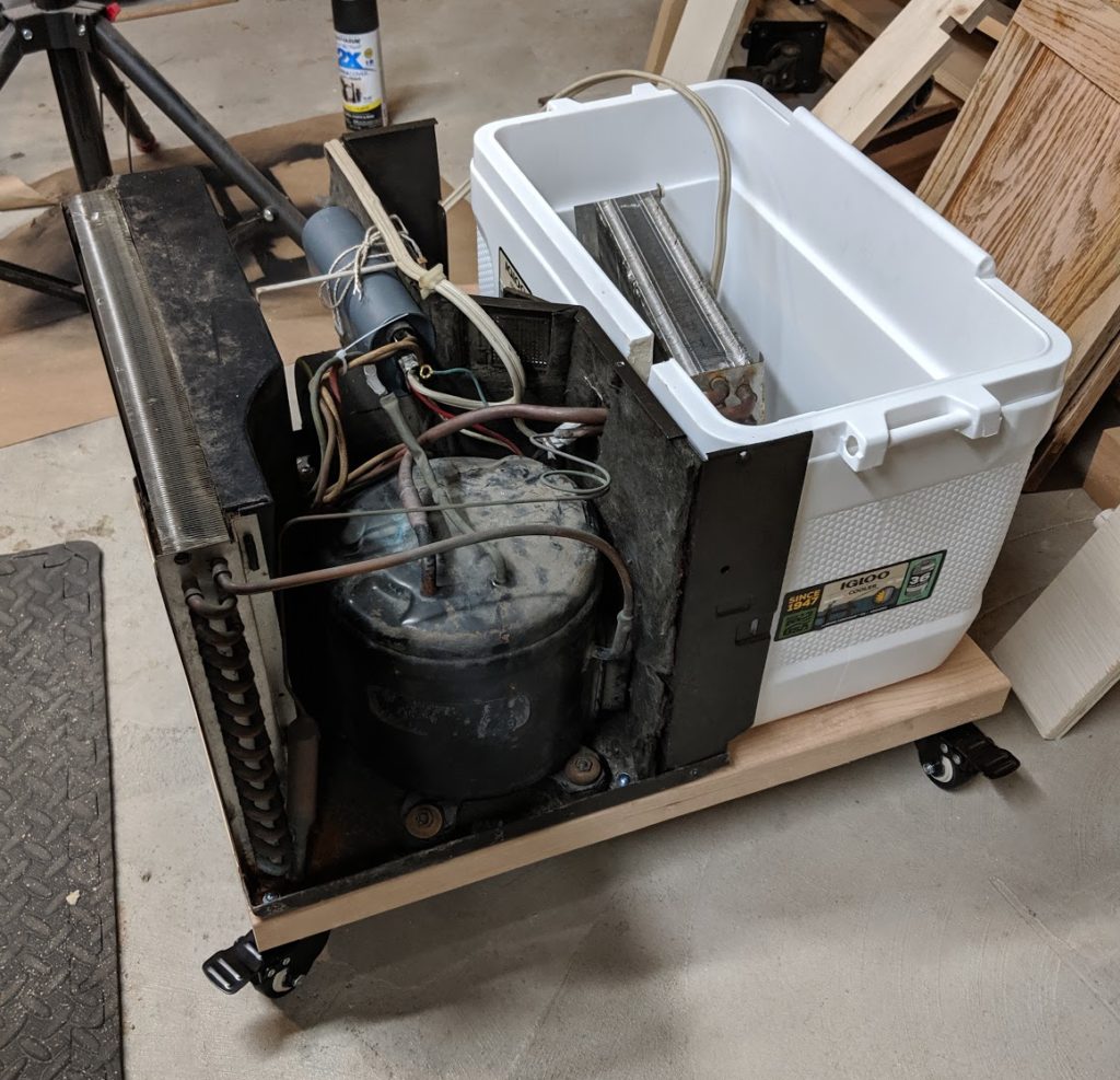
After mounting everything, I built a frame to protect both the unit, and the operator. The frame needed to allow for airflow on the hot side, to let air out through the heat exchanger.
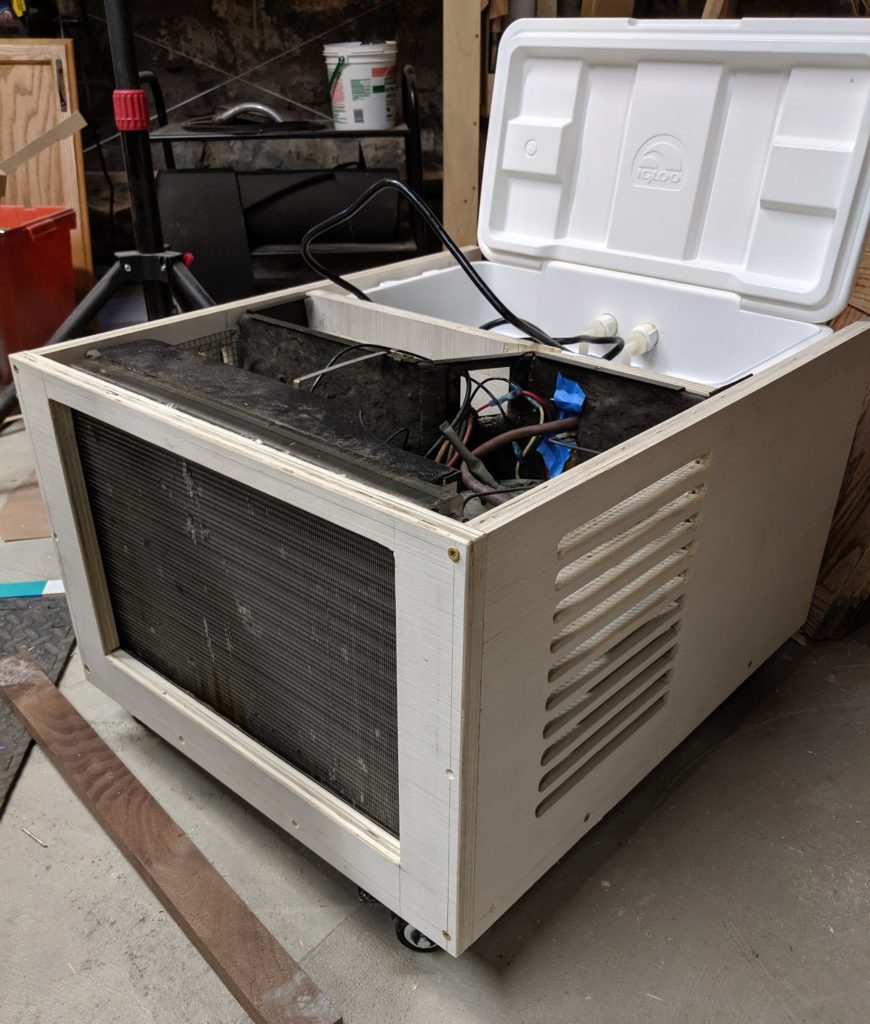
The vent holes ended up being large enough to fit fingers through, so chicken wire was added to make it safer.
On the electronics side, an air conditioner typically uses a basic thermostat control mounted in the unit. I needed a probe that could be moved into the glycol tank. I went with a custom control using an Arduino. To make the new controller work I had to remove the existing AC controls, and wire the unit to be “always on” when powered up by the Arduino. All the old switches were cut out and the fan was permanently wired to “high”.
I also decided that it would be much more efficient if I circulated the glycol through the heat exchanger when the unit runs, so I took the time to wire that into the whole system. This meant that, in total, the system needed to control a fan, a pump, and the compressor, with the fan and compressor wired through a starting capacitor.
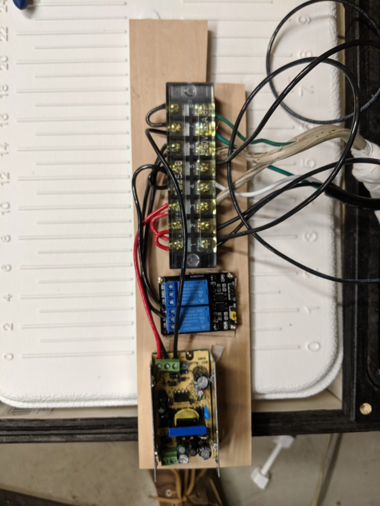
All the power wires were attached to a bus, with the relay and the power supply for the Arduino.
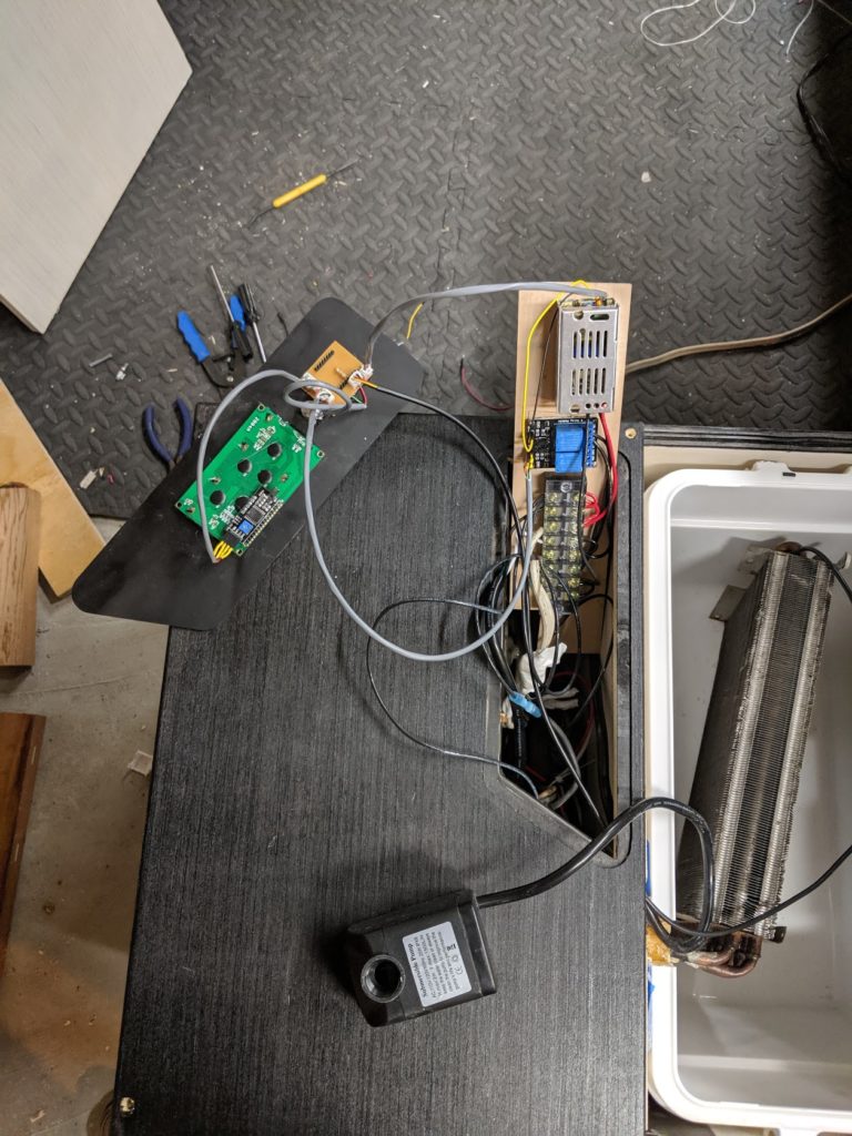
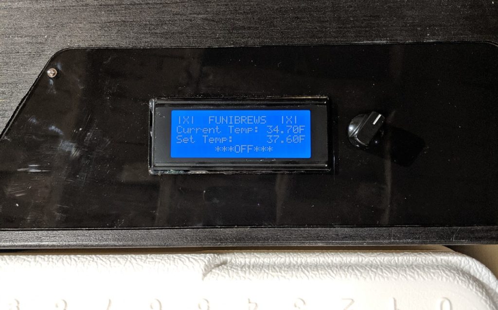
On the controller, a screen was added so I could interact with the temperature settings. The housing of the unit was cut to add a window for the display screen. A basic analogue knob was also mounted to serve as the only control.
With everything wired up, I worked on the code side of things. The code ended up being very basic, reading the value of the knob, and mapping it to a range of 0-50F. The system polls a 1-Wire temperature probe and the knob position every 10 seconds. If the value of the temperature probe raises above the set temperature (plus a small buffer zone), the unit activates the attached relay, until the temperature falls to below a set buffer below the temperature setting. Feel free to email me if you are working on your own and want the code.
To get the glycol out of the unit, barb fittings were added. Eventually, I’ll add more barns so that it can control more than one fermenter at a time. For each pair of barb fittings, a pump is added to the reservoir.
I also built a temperature controller for the fermenter itself, that I will write a future article on. As a preview, here is everything in operation and running.
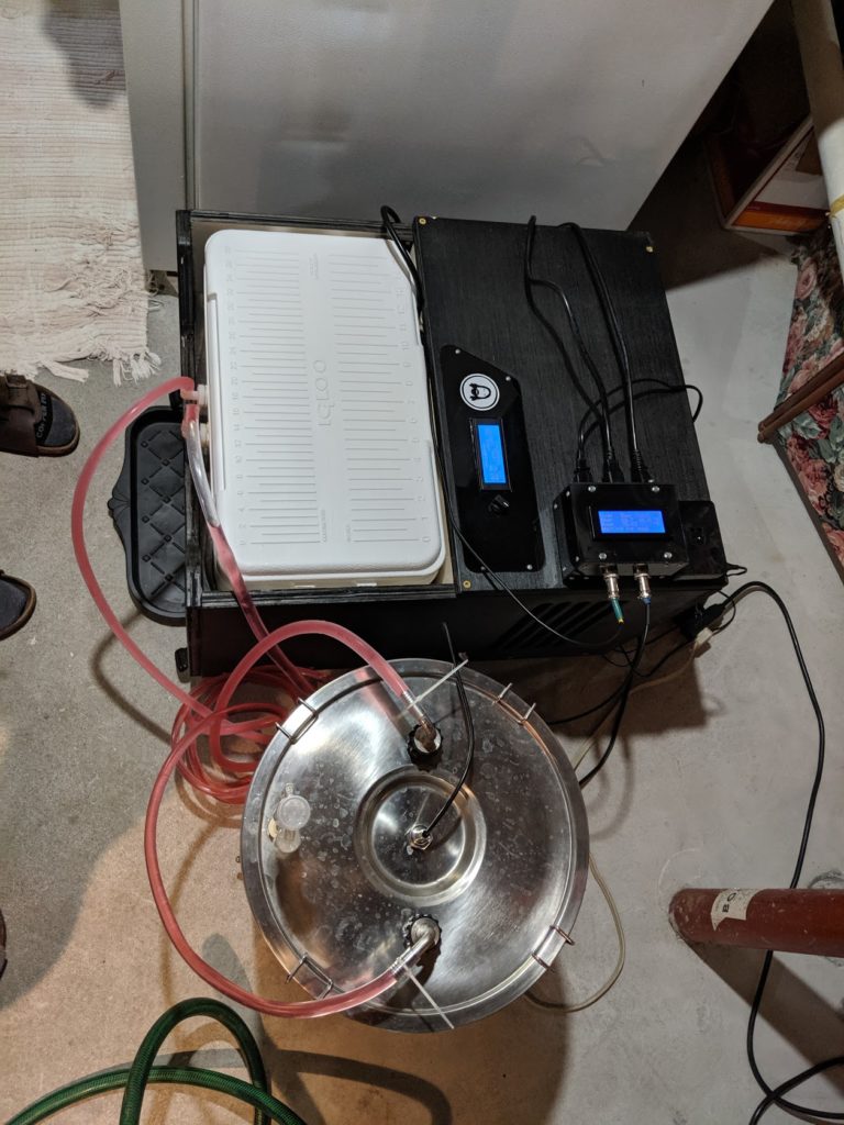
Stay tuned for details on the little black box temperature controller pictured above.
Batman Bookshelf
A friend of mine (an excellent woodworker himself) mentioned he had a coworker who was looking for a Batman book shelf, and showed me a photo of what he had in mind. He felt this project was more up my alley and I agreed that it was something I’d be interested in trying my luck on.
I spoke with his coworker and agreed on dimensions. The shelf would be 2 pieces totaling 4 ft wide, with a depth of 8 inches.
I considered making the shelves out of a laminated stack of CNC cutouts. While this certainly would have been the easiest approach, It would have required 8 sheets of 3/4″ MDF, and left a lot of unusable scrap.
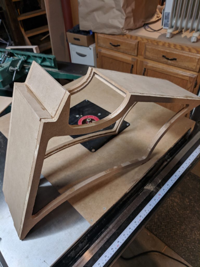
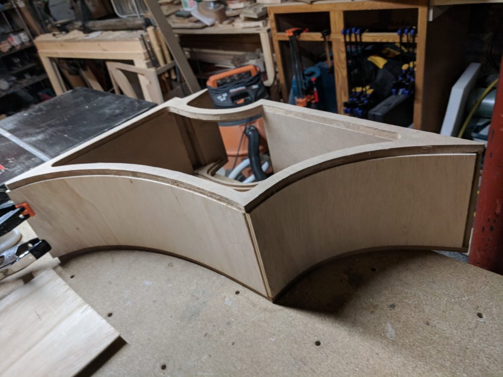
I settled on a more labor intensive, but resource friendly approach. For starters, I CNC cut a front and back frame for each side of the shelf.
Each of these frames had a 1/4″ rabbit cut as part of the CNC program. This rabbit allowed for paneling to be attached joining the front to back.
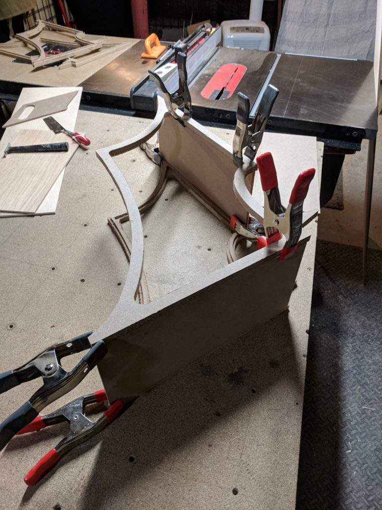
I glued up all the flat surfaces of the shelf first to define the 3D structure. The 1/4″ MDF fit perfectly in the CNC cut rabbits. Bellow; I add a temporary cross piece to keep things square.
For the curved surfaces I considered a number of options, but settled on Wackywood, a type of plywood designed with the each ply oriented in the same direction. This orientation allows the sheet to bend in one direction while staying stiff in the other.
I had never used Wackywood, and was disappointed to find that while most sheet products fall under their nominal dimensions (a typical sheet of thin ply or MDF is around 1/32″ undersized) Wackywood was actually over-sized, measuring in closer to 3/8″. More on this later…
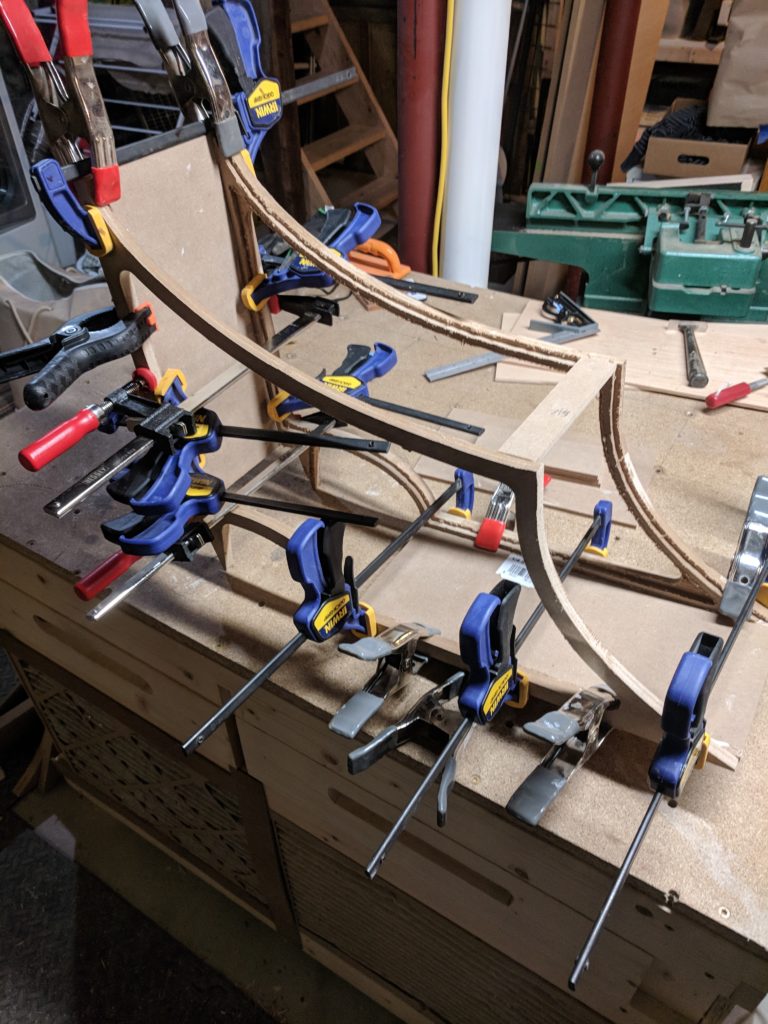
I wrestled the sheets through my table saw ripping them to match the width of the MDF panels already glued up. Using a string to follow the curves of the front and rear frames, I was able to measure and cut the Wackywood to length.
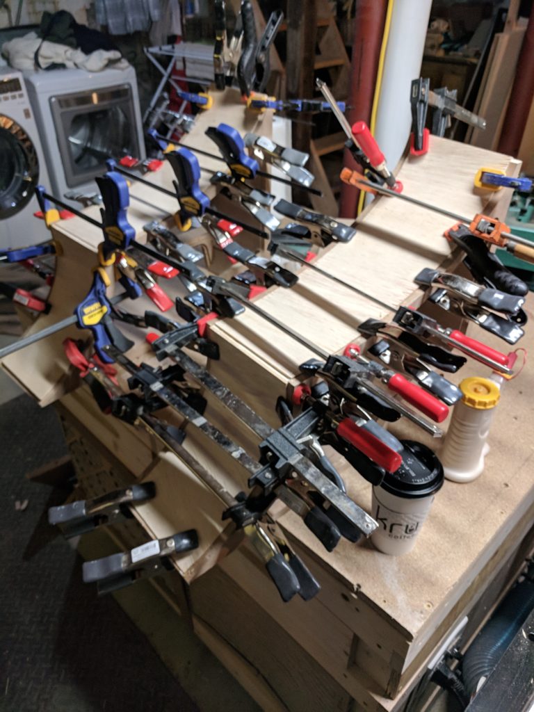
After using every spring clamp I own then running to the store for more, I pieced in the curved sections and glued them. I did the outsides first, then filled in the insides.
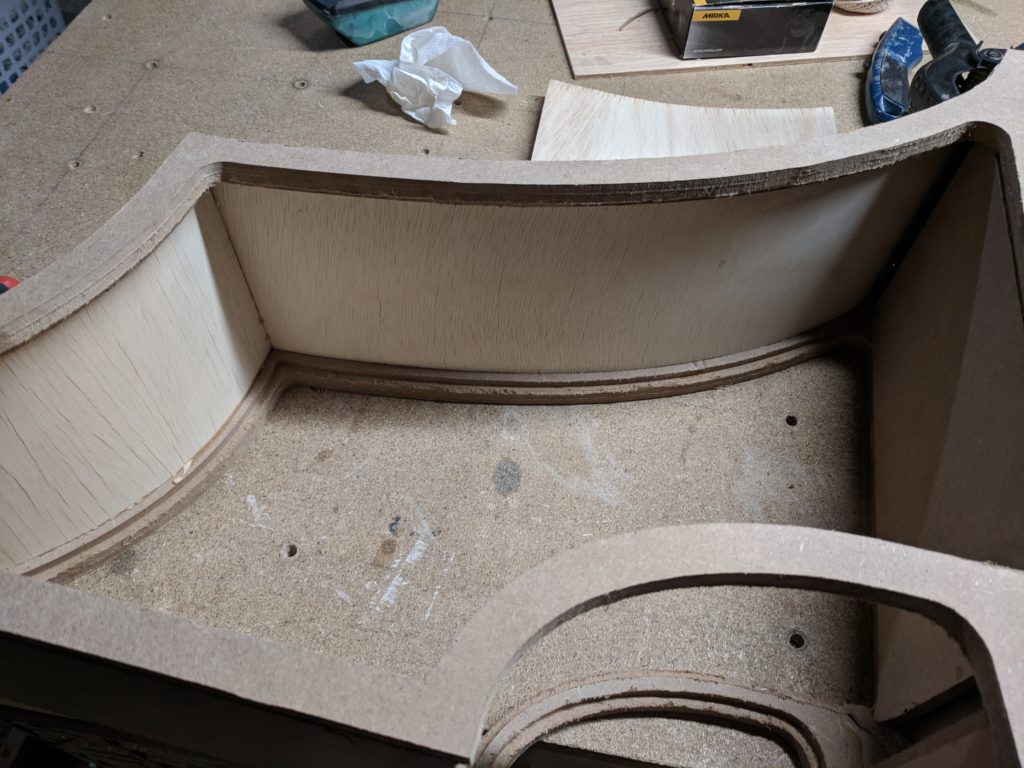
I sadly missed a number of steps as far as photos go, but the next step was to fix the step created trying to fit the thick Wackywood into the 1/4″ rabbit. I ripped down pine strips to match the thickness of the step, and edge banded the MDF. In some of the tighter curves, I needed to soak the pine to soften it before clamping it into the bend.
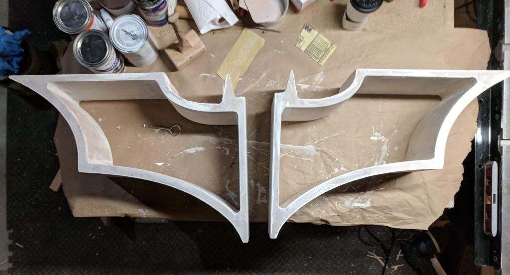
To create all of the very tight radii (the ear curves and inside fillets) Bondo body filler was applied and sculpted. While this method worked, it required lots and lots of sanding; everyone’s favorite.
Once I was happy with the sanding (or I should say too tired and dusty to continue any more), a thick primer was brushed on to further cover up the Wackywood’s crackled texture and any minor pocks in the Bondo. Some wood filler was used to skim coat the particularly bad areas, followed by some more sanding.
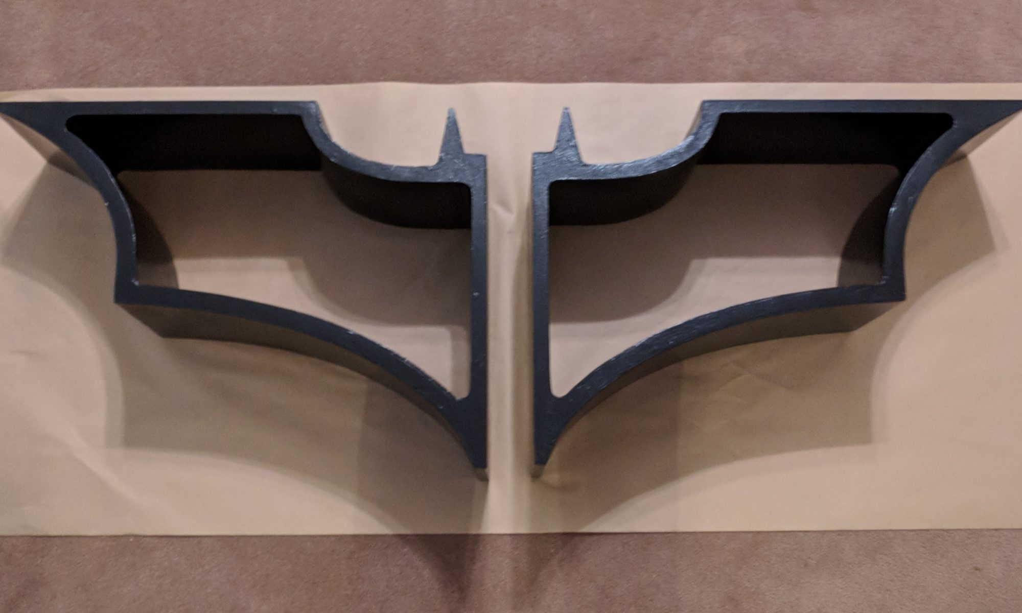
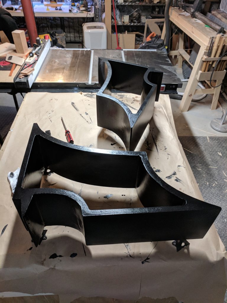
Finally it was time for painting. It just wouldn’t be right if it wasn’t deep black. Four coats of paint were applied using a foam roller. The roller left a nice “orange peel” texture, giving the shelf an almost metallic texture as well as hiding imperfections.
The customer was very excited to see the Batman shelves!
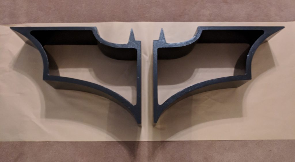
I am very curious to see how this looks loaded up with books on a wall.
Hello!
